Latest Videos


Quantum Spectrum - a DSP option for SDRs
and maybe ALL radios (someday)
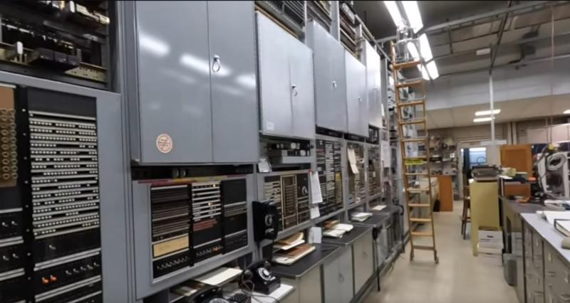
At the Connections Museum in Seattle
the insane telephone technology that led to today's computers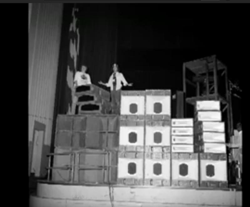
The Story of Heil Sound
Rock and Roll Hall of Fame presentationLatest Blogs
Latest Audio

The Birth, Life, and Death of the Cosmophone
As told by the inventor, Butch Mason W6KAG. Recorded by K6VOI in 1970


Sea Rad MM-50 marine radio
audio from the DX-60 Net Nov. 14, 2021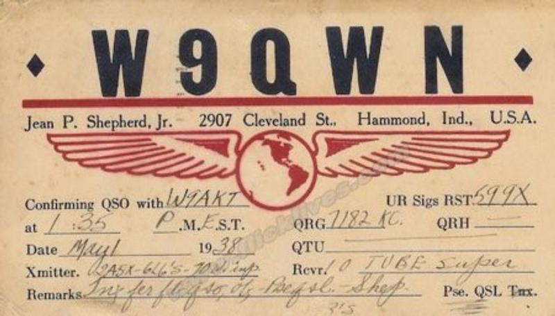
Jean Shepard K2ORS, "Ham Radio" (aka "Heising Modulation")
originally broadcast Jan. 29, 1965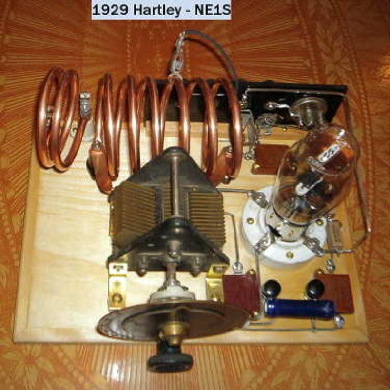
NE1S - Larry from Gray, Maine, operating a 1929 Hartley transmitter
Recorded 11/9/19 on 40 meters
Final Call for N8ECR (SK) - Midwest Classic Radio Net 12/8/18
Harry N9CQX and Bill K8DBNLatest Links


RAN Technology Gallery Images
Gallery: Vintage
The only identifying information on this aircraft transmitter and receiver is the name "Northern" on the panel. Could this be the Northern Radio Company from Seattle that made commercial and marine equipment in the 1950s and 60s?
The purpose of this set was to communicate with air traffic control after a plane left VHF range, including position reports, weather advisories, and for traffic control purposes. Because two-way communications over 100 miles or greater was needed the plane and ground station both used MF or HF frequencies in the 2-6 MHz range. This set was equipped with crystals for 5 transmit and 4 receive frequencies, plus had a tunable receiver that covered LF as well. At some point airborne communications moved from AM to SSB but this set was clearly from an earlier time, probably the 1950s.
The power supply and transmitter modulator were located remotely (and obviously missing). It should not be difficult to build or adapt to an existing power supply/modulator. This configuration remained the standard for many years with remotely located power supplies and modulators for VHF nav/com radios. High-end HF radios such as the Collins 618-S were completely remote with only a small control panel in the cockpit. My guess is that this "Northern" radio was installed in a smaller aircraft such as a King Air, Convair 580, or even a DC-3 where HF comms were required.
I'm interested in learning anything about this radio, the company who made it, FAA/FCC regulations related to its use, and anything about similar equipment, including that made by Bendix, Sunair and others.
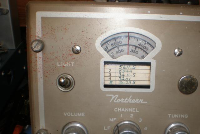
Receiver front panel
Posted: 05/30/2020 (ranickels)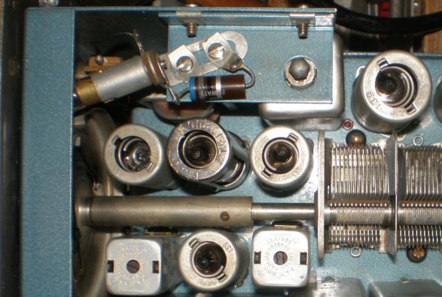
Receiver top view
Posted: 05/30/2020 (ranickels)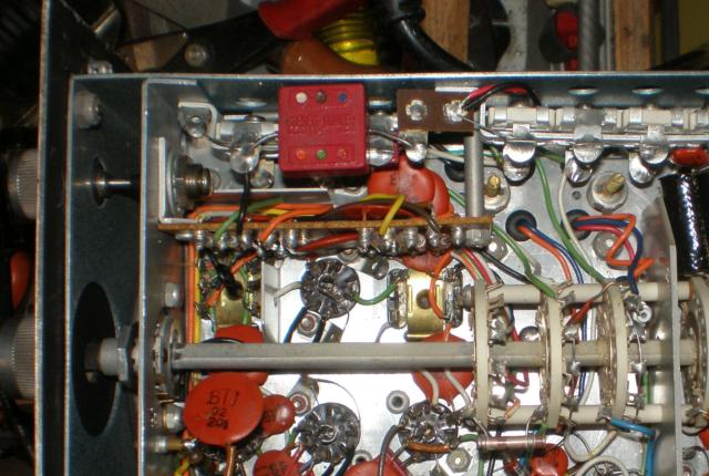
Receiver under chassis view
Posted: 05/30/2020 (ranickels)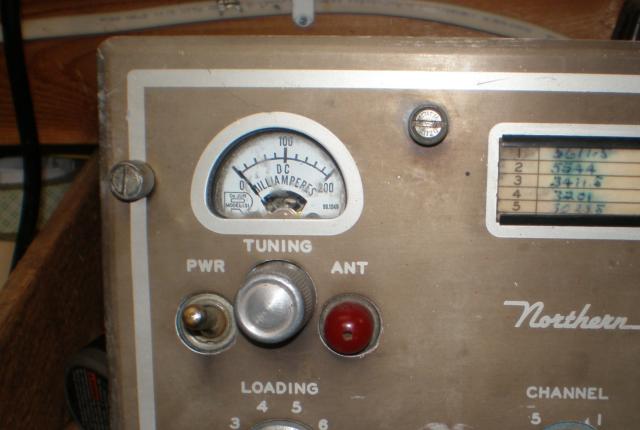
Transmitter front panel
Posted: 05/30/2020 (ranickels)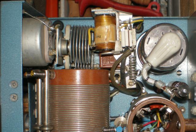
Top view of Transmitter - 6146 PA tube
Posted: 05/30/2020 (ranickels)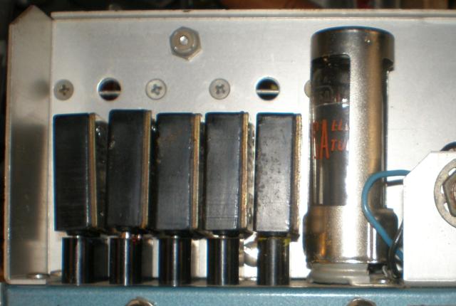
Transmitter rear panel
Posted: 05/30/2020 (ranickels)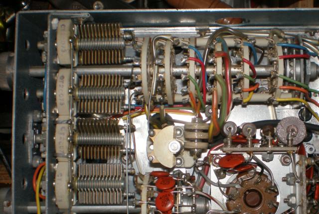
Transmitter under chassis view
Posted: 05/30/2020 (ranickels)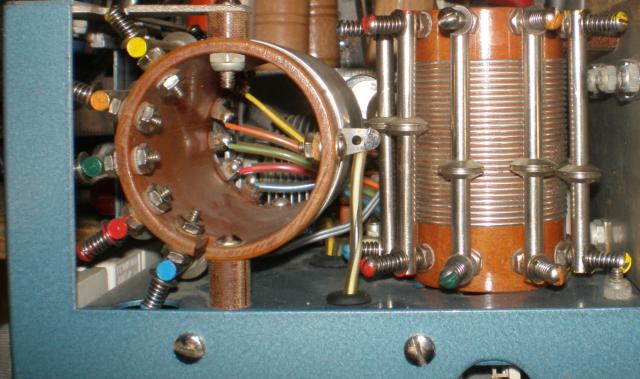
Transmitter coils
Posted: 05/30/2020 (ranickels)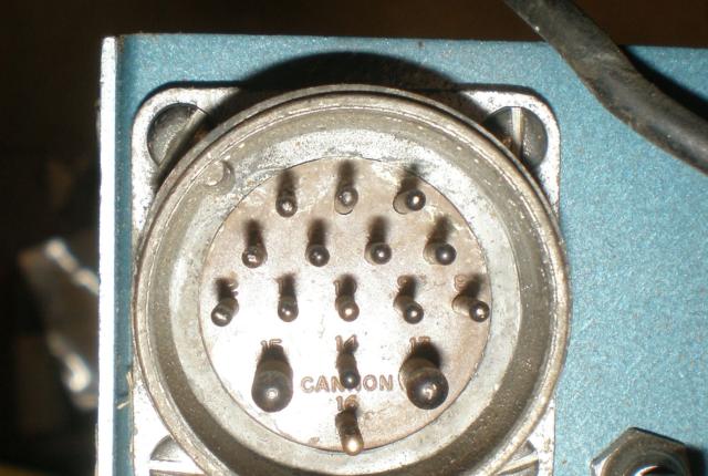
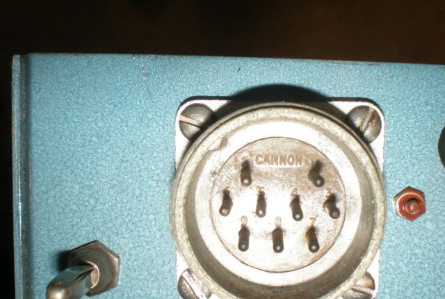
Transmitter connector
Posted: 05/30/2020 (ranickels)