Posted By: Robert Nickels (ranickels) Posted: 11/25/2023 Historic 11/25/2023 |
TV Duplexer |
|
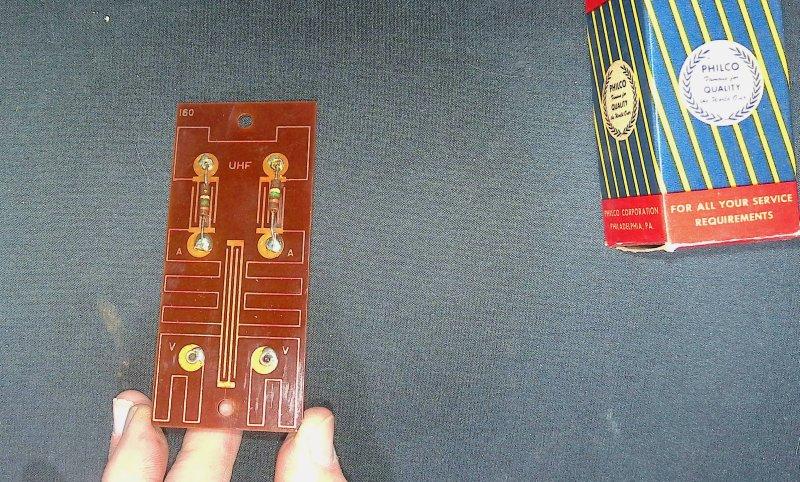
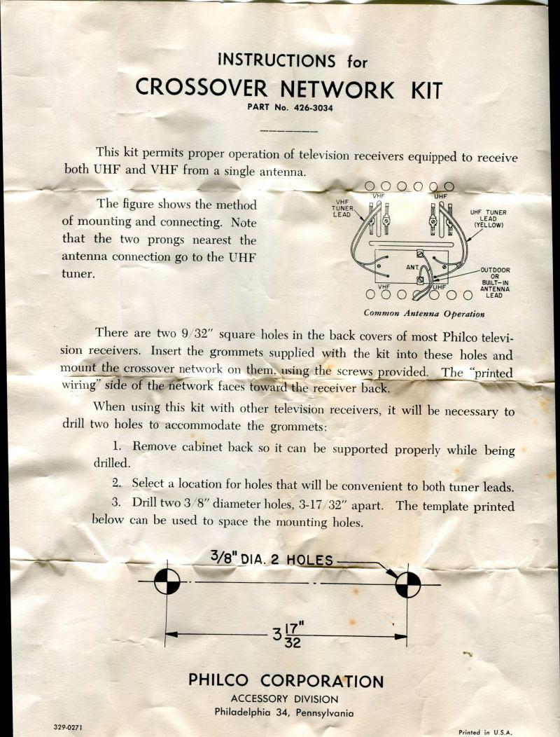
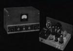
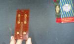
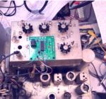
Some things are interesting, even if totally useless nowadays. Such is the case with the Philco 426-3034 Crossover Kit for UHF TV. What the heck is that? Well, back in the late 50s, UHF television stations operating on channels 14-83 started to appear in many areas of the US where viewers had a VHF-only TV antenna, and in many cases an externa UHF converter was required. Tese barriers meant UHF viewership remained low. To speed the growth of UHF broadcasting, in 1962 Congress passed the All Channel Receiver Act, which provided "that the Federal Communications Commission shall "have authority to require that apparatus designed to receive television pictures broadcast simultaneously with sound be capable of adequately receiving all frequencies allocated by the Commission to television broadcasting". This put UHF stations on par with the established VHF stations. To receive UHF signals, set owners needed to put up a UHF antenna, or to replace their existing antenna with one capable of receiving both VHF and UHF signals. If the took the latter approach, which was promoted by TV dealers because there was more money in it - a new problem arose: how to attach a single new twinlead feedline to the TV receiver that had separate antenna terminals for VHF and UHF? Philco's answer was the 426-3034 Crossover Kit. In ham terms, it was what we'd call a duplexer - a device that could allow a single antenna to be used on two different frequency bands without interference. What is interesting is HOW Philco designed it. As the photos show, the crossover kit was built almost entirely on a printed circuit board, which was still fairly new technology at the time. The circuit includes inductors and capacitors, both fabricated by traces on the PC board. Zig-zag lines are inductors, and those with interleaved fingers are capacitors, forming tuned circuts that would separate the two signal bands, along with a pair of carbon comp resistors. There were no CAD systems in those day, no modelling software to simulate the performance. Each element was created by hand calculations from first principles, such as the dielectric characteristics of the material and area of conductors. At most the engineer who designed this device might have had the use of a Monroe calculator for some of his calculations, but changes are good that most of the work was done with slide-rule, pencil and paper. Prototype boards would have been etched and the result tested in the lab, using vacuum-tube based test equipment. Today, many hobbyists could duplicate this task using tools like ELSIE to design the network and LTSpice to simulate how it worked, then lay out the board with KiCad. All these are very powerful Computer Aided Design software tools that are completely free! Things have chaged a lot to be sure, but looking at how things were done in the past can be educational. And the truth is, the same need would probably be addressed in a very similar way today.
|
|
Related Images
Click on the image title or on the image itself to open the full-sized image in a separate window.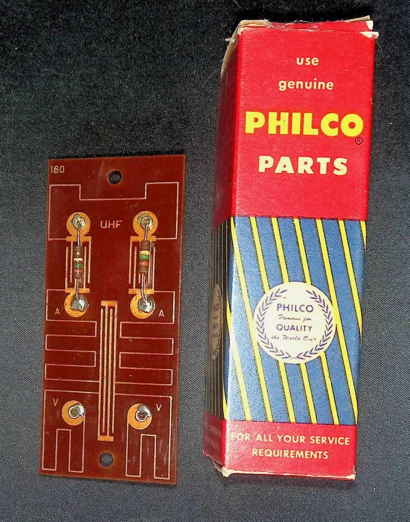

Latest Articles
|
Crystal Replacement
Posted: 02/38/2024
Comments: 0 |
How good can a crummy receiver be?
Hundreds of different simple SDR receivers have been designed around Dan Tayloe's Quadrature Sampling Detector or QSD. Mine add nothing to the state of the art, and in fact subtract things, as I like minimalist solutions and the QSD is right in that sweet spot. Following the evolution of Tayloe's design I delete the resistors in series with the sample lines for inst... READ MORE |
Technical
Posted: 02/37/2024
Comments: 0 |
What's in a number (3253)?
The FST3253 dual four-to-one mux/demux IC has long been used as a "Tayloe Detector" or QSD (and QSE) in low-cost SDRs. They provide incredible performance for such a simple circuit, converting RF to baseband IQ with low loss and the ultimate in simplicity. Unfortunately the original FST3253 part has become obsolete and while substitutes are available, this is where the... READ MORE |
Vintage Ham Radio
Posted: 02/32/2024
Comments: 0 |
The Stancor 10P Transmitter
There weren't really many commercial transmitters in the 1930s as most hams built their own. But many of the ones that were offered came from the transformer companies who had two chances to profit. First, from those who would buy the kit, and two, from those would would see it in the (free) booklets the companies provided to their distributors who would then sell the iron to ham... READ MORE |
Vintage Ham Radio
Posted: 12/355/2023
Comments: 0 |
The Care and Feeding of the EF Johnson Courier amplifier
The EF Johnson "Courier" is a grid-driven amplifier using two 811A tubes. Switching is provided for operating in either class C for CW or as a class B linear amplifier for AM or SSB. Rated power is 500 watts input for CW, 500 watts PEP input for SSB, and 200 watts input for double-sideband AM with carrier. Since all amateur power levels were meas... READ MORE |
Historic
Posted: 11/329/2023
Comments: 0 |
TV Duplexer
Some things are interesting, even if totally useless nowadays. Such is the case with the Philco 426-3034 Crossover Kit for UHF TV. What the heck is that? Well, back in the late 50s, UHF television stations operating on channels 14-83 started to appear in many areas of the US where viewers had a VHF-only TV antenna, and in many cases an externa UHF converter was... READ MORE |
Crystal Replacement
Posted: 11/327/2023
Comments: 0 |
Replacing failed crystals
For decades, quartz crystals were used everywhere a stable frequency source was needed, even in some applications that depended on overtone (harmonic) behavior into the VHF range. These crystals were less stable and more dependent on circuit parameters that fundamental types and thus more problematic. Such was the case with the 94 MHz crystal in the 2 meter converter ... READ MORE |
Historic
Posted: 11/315/2023
Comments: 0 |
My Own Ham Radio Story by W9RAN
Everyone has a story of how they got involved in ham radio - this is mine. It started much earlier, including receiving a Knight Kit Span Master shortwave radio for Christmas in about 1963, at age 12. I'll never forget the night my dad and I finished building it and I wanted to try it out. It came with a 50 ft. antenna which was still coiled up - but ... READ MORE |

Technical
Posted: 09/267/2023
Comments: 0 |
Hot to simulate vacuum tubes in LTSpice
LTSice is a powerful simulation tool that is provided free by Linear Technology Corp. It comes with a complete library of passive and common analog solid-state components but if you want to use it to simulate vacuum tubes, it doesen't work as-is. Even though triode and pentode symbols can be found in the "Misc" folder, they are just schematic symbols and... READ MORE |

Friends Remembered
Posted: 07/208/2023
Comments: 0 |
Merv Schweigert, K9FD (SK)
Comments from Robert Nickels W9RAN, July 27, 2023: There is nothing worse for a ham radio operator than to see a beloved friends callsign with the letters "SK" behind them. Yet sadly, that's what happened on July 23, 2023, when I learned of the passsing of Merv Schweigert, K9FD. While many of our ham radio interests were different - Me... READ MORE |
Vintage Ham Radio
Posted: 01/19/2023
Comments: 0 |
"Winter Projects"
I know many of us who enjoy restoring and repairing vintage gear look forward to winter when there is less competition for time and energy, and a chance to really make a dent in our "to be fixed" piles. A couple of years ago I set time aside for "Heathkit Singlebander Week" and went through every one of them I had, with the result that they're all working ... READ MORE |